
This project was used to time a vehicle around a track by using a sonar sensor to detect when the vehicle passed by. What made this project challenging is wanting to use current components which included using a 16 channel multiplexer to drive the 4 digit 7-segment display instead of a display driver. This proved to be challenging code wise and revealed various problems that had to be solved from using such an unconventional way to display the digits. The project needed to be able to detect when the vehicle first passed the sensor to begin timing. Once the timer started, there needed to be a way to make sure the timer was not false triggered while the vehicle was still passing by the sensor. The timer must also be able to display the previous lap time long enough when the vehicle passed the sensor for a user to read the lap time while the next lap was still being recorded. Lastly, the timer needed to keep track and display what lap the vehicle was on. For this particular project, only three laps needed to be recorded.
The 4 digit 7-segment display was the clock display used for this project (the 7FR5643AS). The clock display shown below in Figure 1, contained 12 pins shown in Figure 2. Pins 6, 8, 9, and 12 represent each digit and needed to be activated one by one in order to multiplex each LED.
Figure 1 – Pin out of 4 segment clock display

Figure 2 – Internal circuit of 4 segment clock display
This particular clock display is a sink activated display so the pins to activate each digit needed to be grounded. NPN transistors (the P2N2222A) were used with 1KΩ resistors for this. For the multiplexer, the CD74HC4067E 16 channel multiplexer was used since they were readily available. Only eight channels were actually used in order to drive the clock display. One problem that cropped up was since the display was driven by the multiplexer was that the channels on the multiplexer needed to be changed very fast to show the numbers correctly. Initially, the channels were changed as soon as the LED was turned on but it was discovered that there was a capacitance in the multiplexer itself that was causing all the LEDs to turn on no matter what numeric value was trying to be displayed. After a few tests, a 500 microsecond delay was added in between each LED activation in order to allow the capacitance nature of the multiplexer to drain before switching to the next channel. Figure 3 shows the pin out of the 16 channel multiplexer. The common port was connected to 5V and 8 channels were used for the 7 LEDs for each digit plus the colon in the middle. 12KΩ resistors were used for each LED segment.
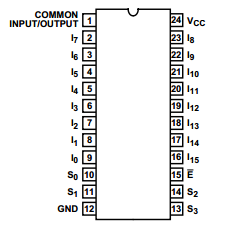
Figure 3- Pin out of 16 channel multiplexer
The HC-SR04 ultrasonic sensor was used to detect the vehicle completing a lap. These sensors are similar to the PING sensor but require an extra pin. These were used for a previous project and showed to have a centimeter accuracy up to 4 meters. Even with the extra pin needed, they carried the same accuary as the PING sensor but were 4-5x cheaper from Amazon here. The datasheet found here shows a simple pulse function can be used to calculate the distance. Dividing the return value by 148 allowed for conversion to inches. The pin out for the sensor is seen in Figure 4.
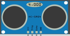
Figure 4 – Pin out for the ultrasonic sensor
Two LEDs with 1K resistors were used for the lap counter. Only two pins were available on the Arduino so the three laps were represented in binary form. The total schematic is shown in Figure 5. Looking back, the common port could hold one 12K resistor so that each LED segment can be directly tied to the multiplexer saving on resistors.
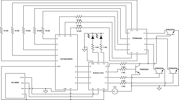
Figure 5 – Full schematic of timer circuit
The code for the timer became overly complex as it required the timer to not false trigger while the vehicle was still passing by the sensor. The timer was also required to show the lap time long enough for a reader to comfortably read while still recording the next lap time. In order to do this, the vehicle was given a five second leeway to pass by the sensor. While these five seconds were passing, the previous lap time was displayed (all zeros if the first lap). Once the five seconds were passed, the display went back to showing the current lap time. In order to display each digit using the multiplexer, the current time needed to be split up into each digit and compared against an array of length seven that represented each LED segment. Overall, using the multiplexer to drive the clock display required a lot more work than would be needed if a simple display driver was purchased. Either way, it was quite a learning experience code wise to manually drive the display with a multiplexer. A video of the timer project is shown below along with the full code.
// multiplexer pins
int muxS0Pin = 2;
int muxS1Pin = 3;
int muxS2Pin = 4;
int muxS3Pin = 5;

// digit pins
int digitZeroPin = 8;
int digitOnePin = 9;
int digitTwoPin = 10;
int digitThreePin = 11;

// led pins
int LED0 = 12;
int LED1 = 13;

// sonar sensor pins
int trigPin = 6;
int echoPin = 7;

unsigned long currentTime = 0; // current running time
unsigned long lastTime = 0; // last time the sensor was triggered
unsigned long delayTime = 5000; // time to delay stop timer for sensor

// digits to display
unsigned long displayTimeDigit0 = 0;
unsigned long displayTimeDigit1 = 0;
unsigned long displayTimeDigit2 = 0;
unsigned long displayTimeDigit3 = 0;

long distance = 0; // min distance to trigger sensor
long thresholdDistance = 10; // max distance to trigger sensor
boolean didCarPassSensor = false; // initial boolean for start of sensor
boolean didCarHitSensor = false; // boolean if sensor is triggered again after start
int timeToDelay = 5000; // time to delay sensor reading again
int lapCounter = 0; // counter of lap

// to setup multiplexer to show each number - next line shows 4bit number of each segment in led
//0000 bottom left, 1000 bottom, 0100 dot, 1100 bottom right, 0010 middle, 1010 top left, 0110 top right, 1110 top
int digitZero[] = {0,0,0,0, 1,0,0,0, 1,1,0,0, 1,0,1,0, 0,1,1,0, 1,1,1,0, 1,1,1,1, 1,1,1,1};
int digitOne[] = {0,1,1,0, 1,1,0,0, 1,1,1,1, 1,1,1,1, 1,1,1,1, 1,1,1,1, 1,1,1,1, 1,1,1,1};
int digitTwo[] = {0,0,0,0, 1,1,1,1, 1,0,0,0, 0,0,1,0, 0,1,1,0, 1,1,1,0, 1,1,1,1, 1,1,1,1};
int digitThree[] = {1,0,0,0, 1,1,0,0, 0,0,1,0, 1,1,1,0, 0,1,1,0, 0,0,0,1, 1,1,1,1, 1,1,1,1};
int digitFour[] = {1,1,0,0, 0,0,1,0, 1,0,1,0, 0,1,1,0, 1,1,1,1, 1,1,1,1, 1,1,1,1, 1,1,1,1};
int digitFive[] = {1,0,0,0, 1,1,0,0, 0,0,1,0, 1,0,1,0, 1,1,1,0, 1,1,1,1, 1,1,1,1, 1,1,1,1};
int digitSix[] = {0,0,0,0, 1,0,0,0, 1,1,0,0, 0,0,1,0, 1,0,1,0, 1,1,1,0, 1,1,1,1, 1,1,1,1};
int digitSeven[] = {1,1,0,0, 0,1,1,0, 1,1,1,0, 1,1,1,1, 1,1,1,1, 1,1,1,1, 1,1,1,1, 1,1,1,1};
int digitEight[] = {0,0,0,0, 1,0,0,0, 1,1,0,0, 0,0,1,0, 1,0,1,0, 1,1,1,0, 0,1,1,0, 1,1,1,1};
int digitNine[] = {1,0,0,0, 1,1,0,0, 0,0,1,0, 1,0,1,0, 0,1,1,0, 1,1,1,0, 1,1,1,1, 1,1,1,1};
int digitDot[] = {0,1,0,0, 1,1,1,1, 1,1,1,1, 1,1,1,1, 1,1,1,1, 1,1,1,1, 1,1,1,1, 1,1,1,1};

/*****************************************************************************************
Setup function. Activates all pins and serial port
*****************************************************************************************/
void setup(){

	 Serial.begin(9600);

	 //lap leds
	 pinMode(LED0, OUTPUT);
	 pinMode(LED1, OUTPUT);

	 // sonar sensor
	 pinMode(trigPin, OUTPUT);
	 pinMode(echoPin, INPUT);

	 // make each pin an output pin
	 pinMode(muxS0Pin,OUTPUT);
	 pinMode(muxS1Pin,OUTPUT);
	 pinMode(muxS2Pin,OUTPUT);
	 pinMode(muxS3Pin,OUTPUT);

	 pinMode(digitZeroPin,OUTPUT);
	 pinMode(digitOnePin,OUTPUT);
	 pinMode(digitTwoPin,OUTPUT);
	 pinMode(digitThreePin,OUTPUT);
} // void setup()

/*****************************************************************************************
Setup function. Activates all pins and serial port
*****************************************************************************************/
void loop(){
	 currentTime = millis(); // get current time
	 mainFunction(); // call main function

	 // for debugging
	 //divideTime();
	 //writeTime(displayTimeDigit0, displayTimeDigit1, displayTimeDigit2, displayTimeDigit3);
}

/*****************************************************************************************
Function senses when sonar sensor is activated then displayes lap time when sensor trigged.
*****************************************************************************************/
void mainFunction(){

	 if(!(didCarHitSensor)){
		 if(checkIfSonarIsHigh()){
			 didCarHitSensor = true;
			 lastTime = millis();
			 lapCounter++;
		 } // if sonar is high then go to next step
	 } // if car hasnt hit sensor then only check sensor

	 if(didCarHitSensor && !(didCarPassSensor)){
		 currentTime = millis() - lastTime;
			 if(currentTime > timeToDelay){
			 didCarPassSensor = true;
		 } // if time has passed start showing time
	 } // if car has pass sensor then wait for certain time to display time

	 if(didCarPassSensor){
		 currentTime = millis() - lastTime;
		 divideTime();

		 if(checkIfSonarIsHigh()){
			 didCarPassSensor=false;
			 lastTime = millis();
			 lapCounter++;
		 } // if car has passed sensor again then update lap time
	 } // if car has passed sensor display lap time

	 writeTime(displayTimeDigit0, displayTimeDigit1, displayTimeDigit2, displayTimeDigit3);

	 if(didCarHitSensor)
	 	displayLap();
}

/*****************************************************************************************
take current time and split it up for display.
*****************************************************************************************/
void divideTime(){
	 displayTimeDigit0 = currentTime/10000;
	 displayTimeDigit1 = (currentTime - displayTimeDigit0*10000)/1000;
	 displayTimeDigit2 = (currentTime - displayTimeDigit0*10000 - displayTimeDigit1*1000)/100;
	 displayTimeDigit3 = (currentTime - displayTimeDigit0*10000 - displayTimeDigit1*1000 - displayTimeDigit2*100)/10;
}

/*****************************************************************************************
Recieves 4 digits that were split up and activates each digit on display one by one in
order to upload array to display number.
*****************************************************************************************/
void writeTime(int displayTimeDigit0Temp, int displayTimeDigit1Temp, int displayTimeDigit2Temp, int displayTimeDigit3Temp){

	 //pin low for digital 0 - the rest high
	 digitalWrite(digitOnePin,LOW);
	 digitalWrite(digitTwoPin, LOW);
	 digitalWrite(digitThreePin,LOW);
	 digitalWrite(digitZeroPin,HIGH);
	 getArray(displayTimeDigit0Temp);

	 //pin low for digital 1 - the rest high
	 digitalWrite(digitZeroPin,LOW);
	 digitalWrite(digitTwoPin,LOW);
	 digitalWrite(digitThreePin,LOW);
	 digitalWrite(digitOnePin,HIGH);
	 getArray(displayTimeDigit1Temp);

	 getArray(10); // activates colon

	 //pin low for digital 2 - the rest high
	 digitalWrite(digitOnePin,LOW);
	 digitalWrite(digitThreePin,LOW);
	 digitalWrite(digitZeroPin,LOW);
	 digitalWrite(digitTwoPin,HIGH);
	 getArray(displayTimeDigit2Temp);

	 //pin low for digital 3 - the rest high
	 digitalWrite(digitZeroPin,LOW);
	 digitalWrite(digitOnePin,LOW);
	 digitalWrite(digitTwoPin,LOW);
	 digitalWrite(digitThreePin,HIGH);
	 getArray(displayTimeDigit3Temp);
}

/*****************************************************************************************
Recieves digit to display and passes array representation down to multiplexer.
*****************************************************************************************/
void getArray(int numberToUse) {
	 if(numberToUse == 0)
	 	displayNumber(digitZero);
	 if(numberToUse == 1)
	 	displayNumber(digitOne);
	 if(numberToUse == 2)
	 	displayNumber(digitTwo);
	 if(numberToUse == 3)
	 	displayNumber(digitThree);
	 if(numberToUse == 4)
	 	displayNumber(digitFour);
	 if(numberToUse == 5)
	 	displayNumber(digitFive);
	 if(numberToUse == 6)
	 	displayNumber(digitSix);
	 if(numberToUse == 7)
	 	displayNumber(digitSeven);
	 if(numberToUse == 8)
	 	displayNumber(digitEight);
	 if(numberToUse == 9)
	 	displayNumber(digitNine);
	 if(numberToUse == 10)
	 	displayNumber(digitDot);
}

/*****************************************************************************************
Recieves array representation of number and activates multiplexer pins.
*****************************************************************************************/
void displayNumber(int numberArray[]) {
	 for(int i=0;i<32;i++){
		 // mux has a capacitance that will carry over - wait to drain cap for next led
		 delayMicroseconds(500);

		 digitalWrite(muxS0Pin,numberArray[i]);
		 i++;

		 digitalWrite(muxS1Pin,numberArray[i]);
		 i++;

		 digitalWrite(muxS2Pin,numberArray[i]);
		 i++;

		 digitalWrite(muxS3Pin,numberArray[i]);
	 }
}

/*****************************************************************************************
Checks in sonar sensor is high and retrns boolean values if sensor is high or not.
*****************************************************************************************/
boolean checkIfSonarIsHigh(){
	 digitalWrite(trigPin, LOW);
	 delayMicroseconds(2);
	 digitalWrite(trigPin, HIGH);
	 delayMicroseconds(2);
	 digitalWrite(trigPin, LOW);

	 // Compute distance
	 distance = pulseIn(echoPin, HIGH, 1000);
	 distance = distance/ 148;
	 Serial.println(distance);

	 if(distance > 0){
	 	return true;
	 } else{
	 	return false;
	 } // if sensor detects opject retuen true else retuen false

}

/*****************************************************************************************
display led binary representation of current lap.
*****************************************************************************************/
void displayLap(){
	 if(lapCounter == 1){digitalWrite(LED0, HIGH); digitalWrite(LED1, LOW);}
	 else if(lapCounter==2){digitalWrite(LED1, HIGH); digitalWrite(LED0, LOW);}
	 else if(lapCounter==3){digitalWrite(LED0, HIGH); digitalWrite(LED1, HIGH);}
	 else{lapCounter=1;}
}