The goal of this project was to test out the temperature sensor and LCD screen for a larger long term project. It involves using the DHT22 temperature and humidity sensor to display its output values on a LCD. LEDs were also added as an extra representation of the temperature with 15 LEDs each representing a 2 degree Fahrenheit change in temperature from 60 degrees (green LEDs) to 90 degrees (red LEDs). The LCD screen’s contrast will be controlled with a potentiometer.
The DHT sensors come in DHT11 and DHT22 varieties. The DHT22 is twice the price but has more accuracy, resolution, and range than the DHT11. The DHT11 is adequate for most projects. The datasheet for the DHT22 shown here shows a humidity range of 0-100% and a temperature range of -40 to 80 degrees Celsius. The accuracy for the humidity and temperature are ±2% and 0.5 degree Celsius respectively. The resolution is 0.1% and 0.1 degree Celsius respectively as well. The datasheet provides the pin out and can be seen in Figure 1 below.
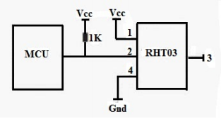
The DHT22 needs a power supply range of 3.3 to 6V. In this project, 5V was given to the sensor. The sensor’s current is about 1.5mA and a pullup resistor with a value of 1kΩ is recommended on the data output.The DHT series sensor are digital sensors that send two 16-bit pieces of data along with an 8-bit checksum. The first 16-bit piece of data represents the humidity and the second 16-bit piece represents the temperature in Celsius. The first bit for the temperature signifies a positive or negative value with one meaning negative.
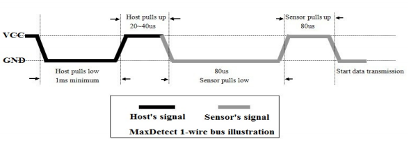
When the sensor is first turned on, the MCU must activate the DHT sensor by sending a pulsed signal. Once the sensor receives the pulse, it sends back a pulse to communicate with the MCU that it is ready to send sensor data. An illustration and recommended timings is shown in Figure 2.
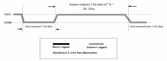
Once the sensor is ready to send out data, it sends out each bit in 50uS increments. The data is read then converted into integer form to be displayed for the user. Another illustration from the datasheet is shown in Figure 3.
The LCD screen is a GDM1602K 16×2 character LCD and it’s datasheet can be viewed here. It is recommended a power supply voltage of 5V and runs at 1.5mA. The LCD stores the incoming data and contains an internal clock that displays the characters independent of the MCU clock speed. The LCD contains a register select and read/write select pins (pins 4 and 5) in order to control the output. There are also four bi-directional bus lines that receive the actual display data from the MCU. The register select pin allows the MCU to move the current cursor position on the LCD matrix to write to the screen. A table of functions such as erase, change cursor position, and read can be found in the datasheet. Once the cursor and settings have been set, a table at the end of the datasheet gives the 8-bit representation of all ascii characters that can be displayed on the LCD. A custom character can also be created by eight arrays of eight bits with each bit representing each pixel in a column and each array representing each row for a character on the LCD. A custom character generator program can be downloaded here.
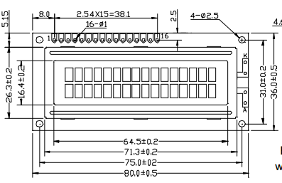
The LCD also contains an operation enable at pin 6 and a contrast adjust at pin 3 that changes the contrast from a varying input voltage range of 0-5V. This contrast input will be controlled by a 10k potentiometer. Pins 11-14 are the DB4-DB7 inputs that actually write the data to the LCD screen. Overall, the LCD screen needs 6 pins from the MCU to function. The LCD pin put and dimensions can be viewed in Figure 4. The code for this project can be found at my github here.
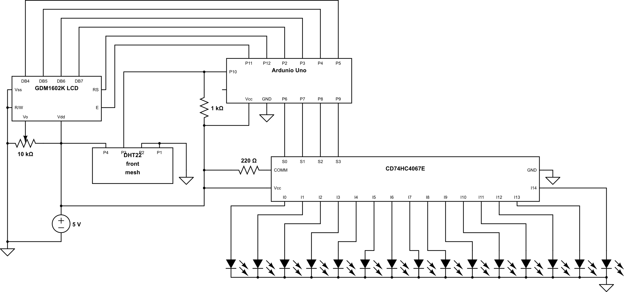
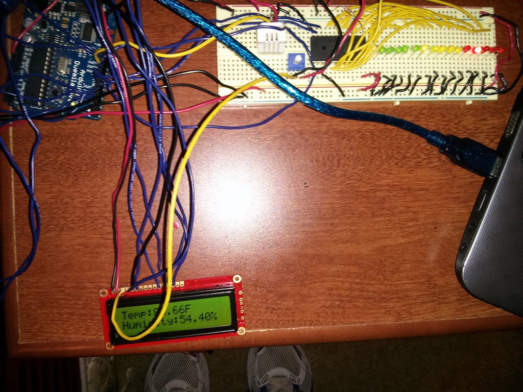
The CD74HC4067E 16 channel multiplexer was used for the LED display because they were readily available. The multiplexer discussed in the lap timer project was used in the same configuration as the previous project but with only one 10k resistor used for the common input pin. The final schematic is shown in Figure 5 along with a picture and code below. Overall, this was a fairly simple project to test the DHT and LCD. The code for this project can be found at my github here.